MDE and Variability Modeling
Table of Contents
Despite their crucial importance, features are rarely modularized and there is only little support for incremental variation of feature functionality. — Groher and Völter (Groher and Voelter 2007)
The employment of model-driven techniques for the engineering of software systems is often accompanied by a shift in focus from individual software products to groups of products with similar characteristics. This may happen tacitly — because the modeling process reveals these commonalities as abstractions (cf. Why Model?) and good software engineering practices such as modularity and reuse create the conditions for their sharing across products — or by explicit design.
Whichever its origins, this type of engineering presents challenges of a different kind, as Stahl et al. note:
[…] MDSD often takes place not only as part of developing an entire application, but in the context of creating entire product lines and software system families. These possess very specific architectural requirements of their own that the architects must address. (Völter et al. 2013) (p. 5)
Thus, much stands to be gained by making the approach systematic, an aim often achieved in the literature by recourse to software diversity techniques such as variability modeling.1
This document is organised as follows. Section Software Product Line Engineering introduces the notion of product lines and connects it to domain engineering. Variability proper is then tackled (Variability Management and Variability Models), followed by a brief introduction on feature modeling (Feature Modeling). The document concludes with Section Integrating Feature Modeling with MDE, where feature modeling is then related back to the model driven approaches.
Software Product Line Engineering
The idea of abstracting commonalities between sets of programs has had a long history within computer science, starting as early as the 1970s with Dijkstra's notion of program families.2 A modern and systematised embodiment of Dijkstra's original insights can be found in Software Product Line Engineering (SPLE) (Pohl, Böckle, and van Der Linden 2005) (Clements and Northrop 2002), which is of particular significance to the present work because its principles and techniques are often employed in a MDE context (Groher and Voelter 2007) (Roth and Rumpe 2015) (Groher and Voelter 2009).
Pohl et al. define SPLE as "a paradigm to develop software applications (software-intensive systems and software products) using platforms and mass customization." (Pohl, Böckle, and van Der Linden 2005) Roth and Rumpe add that "SPLE focuses on identifying commonalities and variability (the ability to change or customize a system in a predefined way) to create components that are used to develop software products for an area of application." (Roth and Rumpe 2015)
The mechanics of SPLE bring to mind Stahl et al.'s dual track process, in that Domain Engineering is used to create a set of core assets and Application Engineering is applied to those core assets in order to develop a family of related products, called a product line or a system family.3 In this light, Domain Engineering defines the variation space available to all products within the product line, opening up possibilities in terms of variability, whereas the role of Application Engineering is to create specific configurations or variants for each product, reducing or eliminating variability. Figure 1 illustrates this idea.
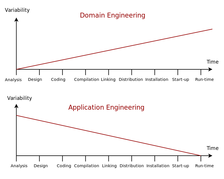
Figure 1: Variability management in time. Source: Author's drawing based on Bosch et al.'s image (Bosch et al. 2001)
The importance of managing variability within SPLE cannot be overstated, nor can the challenges of its management, as Groher and Völter make clear (emphasis ours): "The effectiveness of a software product line approach directly depends on how well feature variability within the portfolio is managed from early analysis to implementation and through maintenance and evolution." (Groher and Voelter 2007) The central question is then how to integrate a model-driven approach with the management of variability.
Variability Management and Variability Models
Like the program families described in the previous section, variation itself has long been a going concern in software development; but, traditionally, it has been handled by programmatic means via techniques such as configuration files, design patterns, frameworks and polymorphism — that is, at a low-level of abstraction — and scattered across engineering artefacts.4 SPLE promotes instead explicit variability management, which Groher and Völter define as "the activity concerned with identifying, designing, implementing, and tracing flexibility in software product lines (SPLs)." (Groher and Voelter 2007) The idea is to promote variability to a first-class citizen within the engineering process.
A variability management approach that resonates particularly with MDE is variability modeling — that is, the use of DSL designed for expressing variability — for much the same reasons MDE promotes model use in general (cf. Why Model?). Stoiber puts variability modeling in context:
SPLE allows maximizing the reuse of commonality (i.e., by developing all products on a common product platform) and of variability (i.e., by a more modular development of variable functionality that can be added to or removed from the product more easily). This requires a variability model, though, to support an efficient specification and development of both the software product line as a whole and of individual application products. (Stoiber 2012)
The benefits alluded to by Stoiber are more clearly identified by Czarnecki, who, in (Czarnecki 1998) (p. 68), sees three main advantages resulting from the explicit modeling of variability:
- Variability Abstraction: By having a model of variability across the system — "a more abstract representation", in Czarnecki's words — it is now possible to reason about it independently of implementation mechanisms, which facilitates the work of Domain Engineering.
- Variability Documentation: From the perspective of Application Engineering, the variability space is made explicit and concise, therefore simplifying decisions around use and reuse.
- Variability Traceability: Engineers can also have a better understanding of the inclusion or exclusion of functionality because the variability model can answer those questions independently of the implementation.
These benefits may help explain the abundance of literature on variability modeling languages and notations, including the Common Variability Language (CVL) (Haugen, Wasowski, and Czarnecki 2013), AND/OR Tables (Muthig et al. 2004), Decision Modeling (Schmid, Rabiser, and Grünbacher 2011), Orthogonal Variability Modeling (OVM) (Pohl, Böckle, and van Der Linden 2005) — to name just a few. A survey of all of these approaches lies beyond the scope of the present work, given our need for a small subset of high-level concepts from the variability domain. Therefore, the focus shall be narrowed instead to a single approach which meets our requirements: feature modeling.5
Feature Modeling
Feature modeling was originally introduced by Kang et al.'s work on FODA (Feature-Oriented Domain Analysis) (Kang et al. 1990) and subsequently extended by Czarnecki and Eisenecker (Czarnecki et al. 2000), amongst many others.6 As the name indicates, the concept central to their approach is the feature, which Groher and Völter define in the following manner: "[products] usually differ by the set of features they include in order to fulfill (sic.) customer requirements. A feature is defined as an increment in functionality provided by one or more members of a product line." (Groher and Voelter 2009) Features are thus are associated with product lines — each feature a cohesive unit of functionality with distinguishable characteristics relevant to a stakeholder7 — and the interplay between features then becomes itself a major source of variability, as Groher and Völter go on to explain: "Variability of features often has widespread impact on multiple artifacts in multiple lifecycle stages, making it a pre-dominant (sic.) engineering challenge in software product line engineering."
Features and their relationships are captured by feature diagrams and feature models, as Czarnecki et al. tell us (Czarnecki, Helsen, and Eisenecker 2005a): "A feature diagram is a tree of features with the root representing a concept (e.g., a software system). Feature models are feature diagrams plus additional information such as feature descriptions, binding times, priorities, stakeholders, etc." Feature diagrams have found widespread use in the literature since their introduction, resulting on the emergence of several different extensions and variations.8 For the purposes of the present chapter we shall make use of cardinality-based feature models, as described by Czarnecki et al. in (Czarnecki, Helsen, and Eisenecker 2005a) and whose notation Figure 2 summarises.
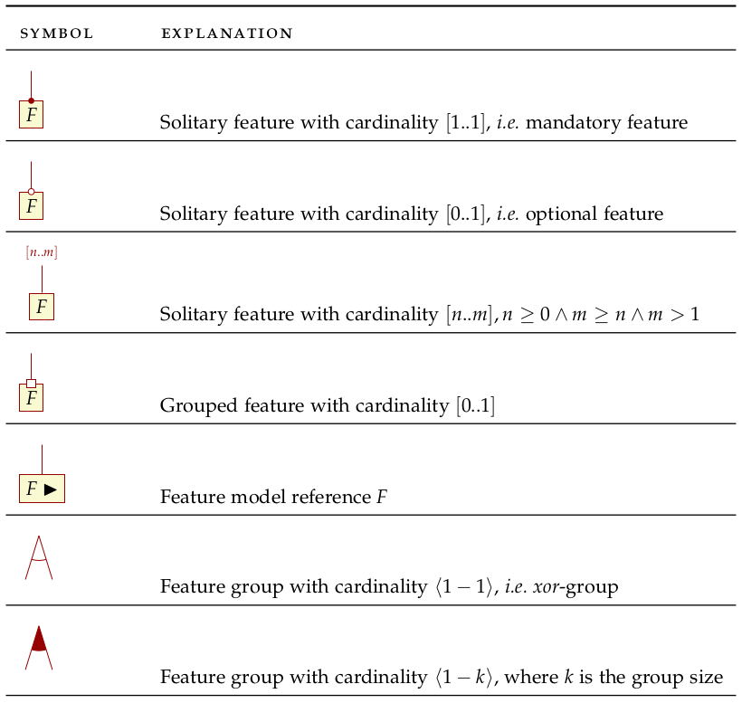
Figure 2: Symbols used in cardinality-based feature modeling. Source: Author's drawing, based on Czarnecki and Helsen (Czarnecki and Helsen 2006)
The notation is perhaps made clearer by means of an example (Figure 3),
which builds on the example from Metamodelling Hierarchy. The top-most node of
the feature diagram (i.e. Car) is called the root feature. Nodes Body,
Engine, Gear and Licence Plate describe mandatory features whereas node
Keyless Entry describes an optional feature. Engine contains a set of
grouped features that are part of a xor-group, whereas Gear contains a set
of features in a or-group. Or-groups differ from xor-groups in that they
require that at least one feature from the group needs to be selected whereas
xor-groups allow one and only one feature to be selected.
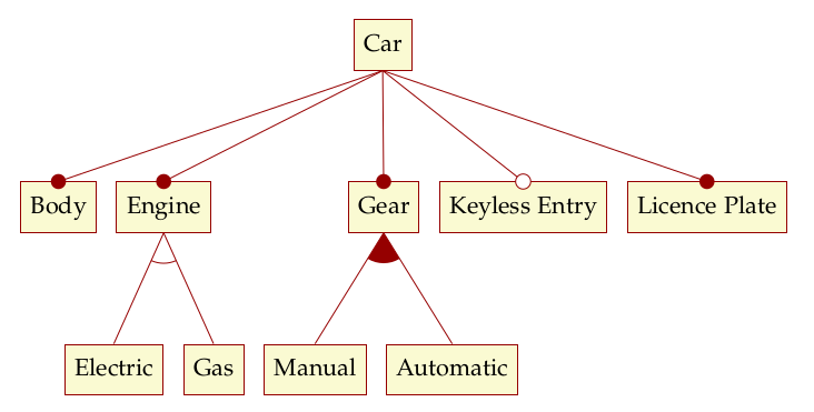
Figure 3: Sample feature model. Source: Author's drawing, modified from a Czarnecki and Wasowski diagram (Czarnecki and Wasowski 2007).
Feature diagrams have the significant property of being trivially convertible into Boolean logic formulas or to a CNF (Conjunctive Normal Form) representation, making them amenable to solving using established solvers such as BDD (Binary Decision Diagram) (Czarnecki and Wasowski 2007) and SAT (Batory 2005).
Importantly, feature modeling also has known shortcomings, and these were considered during our review of the literature. Most significant were those identified by Pohl et al. (Pohl, Böckle, and van Der Linden 2005), namely that feature models mix the modeling of features with the modeling of variability and do not provide a way to segment features by intended destinatary — i.e. it is not possible to distinguish between features meant for internal purposes from those meant for end-users. With OVM, Pohl et al. propose instead a decomposition of responsibilities. Clearly, there is validity to their concerns, as demonstrated by the fact that concepts that OVM brought into attention such as variation points — "delayed design decision[s]" (Bosch et al. 2001) that "[…] allow us to provide alternative implementations of functional or non-functional features" as well as documentation — are now commonly used in the literature, even in the context of feature modeling. Nonetheless, since features provide an adequate level of granularity for our needs, we need not concern ourselves with Pohl et al.'s criticism. We do, however, require a clearer pictured of the relationship between feature models and the kinds of models that are typically found within MDE.
Integrating Feature Modeling with MDE
The crux of the problem is then on how to integrate MDE modeling techniques with variability management — or, more specifically for our purposes, with feature modeling. Clearly, having a feature model simply as a stand-alone artefact, entirely disconnected from the remaining engineering activities is just a form of MBE, as Czarnecki and Antkiewicz explain (emphasis ours): "Although a feature model can represent commonalities and variabilities in a very concise taxonomic form, features in a feature model are merely symbols. Mapping features to other models, such as behavioral or data specifications, gives them semantics." (Czarnecki and Antkiewicz 2005)
Therefore, the availability of concise and interlinked representations of variability across models is a prerequisite to attain this semantically rich view of features. For their part, Groher and Völter argue that integrating variability directly within models has important advantages: "[…] due to the fact that models are more abstract and hence less detailed than code, variability on model level is inherently less scattered and therefore simpler to manage." (Groher and Voelter 2008) (cf. Figure 4).
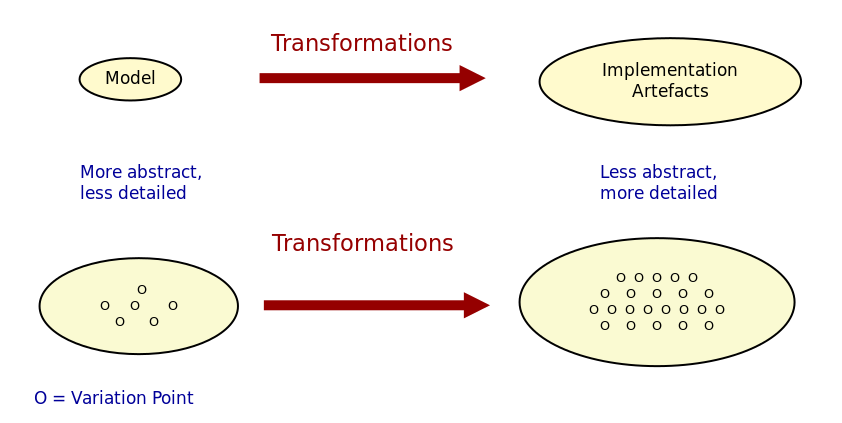
Figure 4: Mapping abstract models to detailed representations. Source: Author's drawing from Groher and Völter's image (Groher and Voelter 2008)
Whilst delving into the conceptual machinery of this integration, Groher and Völter (Groher and Voelter 2007) (Groher and Voelter 2009) analysed the types of variability found in models and proposed dividing it into two kinds, structural and non-structural, defined as follows: "Structural variability is described using creative construction DSLs, whereas non-structural variability can be described using configuration languages." We name these two kinds input variability since they reflect variation within the input models. In their view, the feature model becomes a metamodel for the product line9, and their instances are the configuration models for products, with the final aim being to "[…] use a configuration model to define variants of a structural model." According to them, these variants can be generated in two ways:
- Positive Variability: The assembly of the variant starts with a small core, and additional parts are added depending on the presence or absence of features in the configuration model. The core contains parts of the model that are used by all products in the product line.
- Negative Variability: The assembly process starts by first manually building the "overall" model with all features selected. Features are then removed based on their absence from the configuration model.
Since these two types of variability are related to generation, we classify them
as generational variability. Figure 5
illustrates these two techniques, applied to sample features A, B and C.
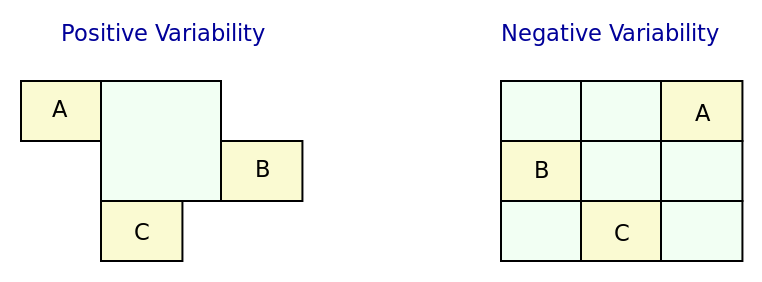
Figure 5: Positive and negative variability techniques. Source: Author's drawing based on images from Groher and Völter (Groher and Voelter 2009)
Given the cross-cutting nature of feature related concerns, Groher and Völter proposed using AOP (Aspect Oriented Programming) (Filman et al. 2004) techniques to implement positive and negative variability, to which they gave the perhaps overly-descriptive name of AO-MD-PLE (Aspect-Oriented Model Driven PLE). AO-MD-PLE has the advantage of considering all stages of software engineering, from problem space to solution space, including models, transformations (both M2M and M2T) and manually crafted code. In our opinion, its main downside is complexity, not only due to challenges inherent to AOP itself (Constantinides, Skotiniotis, and Stoerzer 2004) (Steimann 2006), but also because it uses several different tools to implement the described functionality and, understandably, requires changes at all levels of the stack.
Undertakings of a less ambitious nature are also present in the literature. The simplest approach is arguably to integrate variability modeling directly with UML via a UML Profile, as suggested by Clauß's early work (Clauß 2001), which focused on concepts such as variation points and variants. Ziadi et al. (Ziadi, Hélouët, and Jézéquel 2003) build on from this idea, expanding the focus to product line concepts. More recently, in (Possompès et al. 2010) (Possompès et al. 2011), Thibaut et al. created a UML Profile for feature modeling concepts. Extending UML is advantageous due to its universal nature, but alas, it also inherits all of the challenges associated with the modeling suite. FIXME link to adoption
Others have looked elsewhere. In (Czarnecki and Antkiewicz 2005), Czarnecki and Antkiewicz propose a template-based approach to map feature models to different kinds of models. There, they outline a technique of superimposed variants, in which a model template is associated with a feature model to form a model family. The model template is written in the DSL of the target model, and can be thought of as a superset of all possible models, containing model elements that are associated with features by means of presence conditions. Model templates can be instantiated given a feature configuration: "The instantiation process is a model-to-model transformation with both the input and output expressed in the target notation." The approach is reminiscent of Groher and Völter's positive variability, in that the template provides the overall model and MTs are then responsible for pruning unwanted model elements on the basis of the evaluation of presence conditions.
An interesting feature of superimposed variants are IPC (Implicit Presence Conditions):
When an element has not been explicitly assigned a PC by the user, an implicit PC (IPC) is assumed. In general, assuming a PC of true is a simple choice which is mostly adequate in practice; however, sometimes a more useful IPC for an element of a given type can be provided based on the presence conditions of other elements and the syntax and semantics of the target notation.
IPC facilitate the job of the modeler because they infer relationships between features and model elements based on a deep understanding of the underlying modeling language. For example, if two UML model elements are linked by an association and each element has a presence condition, a possible IPC is to remove both modeling elements if either of their presence conditions evaluates to false. Overall, Czarnecki and Antkiewicz's approach is extremely promising, as demonstrated by their prototype implementation, but in our opinion it hinges largely on the availability of good tooling. Asking individual MDE practitioners to extend their tools to support superimposed variants is not feasible due to the engineering effort required.
The application of variability management techniques to code generators was also investigated, as part of this literature review. In (Roth and Rumpe 2015), Roth and Rumpe motivate the need for the application of product line engineering techniques to code generation. Their paper provides a set of conceptual mechanisms to facilitate the product-lining of code generators, and outlines a useful set of requirements: "The main requirements for a code generator product line infrastructure are support for incremental code generation, specification of code generator component interfaces, support for validation of generated code, and support for individual semantics of a composition operator."
For their part, Greifenberg et al. (Greifenberg et al. 2016) reflected on the role of code generators within SPLE — particularly those that are implemented as product lines themselves: "[…] a code generator product is a SPL on its own, since it generates a variety of software products that are similar, and thus shares generator components potentially in different variants". Their work also introduces the concept of variability regions:
Variability regions (VRs) provide a template language independent approach to apply concepts of FOP to code generators. A VR represents an explicitly designated region in an artifact that has to be uniquely addressable by an appropriate signature.
Variability regions are accompanied by two DSL: LDL (Layer Definition Language) and PCL (Product Configuration Language). The LDL is used to define relationships between variability regions, whereas the PCL defines individual configurations to instantiate variants. Variability regions and their modeling is certainly an interesting idea, but it is somewhat unfortunate that Greifenberg et al. did not link them back to feature models or to higher-level modeling in general.
Finally, Jörges' (Jörges 2013) take on code generation, modeling and product lines is arguably the most comprehensive of all those analysed, given he advocates the development of code generators that take into account variant management and product lines as one of its core requirements (Jörges 2013) (p. 8). Genesys, the approach put forward by Jörges in his dissertation, hinges on a service-oriented approach to the construction and evolution of code generators, anchored on the basis of models: "Both models and services are reusable and thus form a growing repository for the fast creation and evolution of code generators."
Unfortunately, there were several disadvantages with his approach with regards to own purposes; namely, the reliance on a graphical notation for the design of code generators and, more significantly, the tool-specific nature of Genesys which cannot be considered outside of jABC.10 As we have seen, these are in direct conflict with our own views on fitting with existing developer workflows rather than imposing new ones. Nonetheless, Jörges' work was very influential to our own, and we've carried across several features of his argument such as a clear outline of a set of requirements in order to guide the model-driven solution.
bibliography
Footnotes:
For a comprehensive analysis on the state of the art in software diversity, see Schaefer et al. (Schaefer et al. 2012). There, they defined software diversity as follows: "In today’s software systems, typically different system variants are developed simultaneously to address a wide range of application contexts or customer requirements. This variation is referred to as software diversity."
In (Dijkstra 1970), Dijkstra states: "If a program has to exist in two different versions, I would rather not regard (the text of) the one program as a modification of (the text of) the other. It would be much more attractive if the two different programs could, in some sense or another, be viewed as, say, different children from a common ancestor, where the ancestor represents a more or less abstract program, embodying what the two versions have in common."
In Czarnecki's words (emphasis his) (Czarnecki 2002):
Domain engineering (DE) is the systematic process of collecting, organizing, and storing past experience in building systems in a particular domain. This experience is captured in the form of reusable assets (i.e., reusable work products), such as documents, patterns, reusable models, components, generators, and domain-specific languages. An additional goal of DE is to provide an infrastructure for reusing these assets (e.g., retrieval, qualification, dissemination, adaptation, and assembly) during application engineering, i.e., the process of building new systems. […] Similar to the traditional single-system software engineering, DE also encompasses the three main process components of analysis, design, and implementation. In this context, however, they are referred to as domain analysis, domain design, and domain implementation."
Czarnecki denounced this historically "inadequate modeling of variability", stating that "[the] only kind of variability modeled in current OOA/D is intra-application variability, e.g. variability of certain objects over time and the use of different variants of an object at different locations within an application."
The interested reader is directed to Chen et al.'s (Chen, Ali Babar, and Ali 2009) systematic literature review of 34 approaches to variability management, which also provides a chronological background. In addition, Sinnema and Deelstra (Sinnema and Deelstra 2007) authored a broad overview of the field, including surveys of DSL and tooling, as well as performing a detailed analysis of six variability modeling approaches.
Feature orientation attracted interest even outside the traditional modeling community, giving rise to approaches such as FOP (Feature-Oriented Programming), which is "[…] the study of feature modularity and programming models that support feature modularity." (Batory 2003)
Note that we use the term stakeholder rather than customer or end user, taking the same view as Czarnecki et al. (Czarnecki, Helsen, and Eisenecker 2005a) (emphasis ours): "[…] we allow features with respect to any stakeholder, including customers, analysts, architects, developers, system administrators, etc. Consequently, a feature may denote any functional or non-functional characteristic at the requirements, architectural, component, platform, or any other level."
An in-depth analysis of these variants would take too far afield with regards to the scope of the present work. The interested reader is directed to Czarnecki et al. (Czarnecki, Helsen, and Eisenecker 2005b), Section 2.2 (Summary of Existing Extensions), where a conceptual analysis of the main variants is provided.
A view that aligns well with Czarnecki et al.'s idea of a feature model as the description of the set of all possible valid configurations within a system family (Czarnecki, Helsen, and Eisenecker 2005a).
As per Jörges' (Jörges 2013) (p. 43): "jABC is a highly customizable Java-based framework that realizes the tenets of XMDD [Extreme Model-Driven Development] […] jABC provides a tool that allows users to graphically develop systems in a behavior-oriented manner by means of models called Service Logic Graphs (SLGs)."